
Imagine trying to run a city with no roads connecting its buildings, no infrastructure to carry electricity, water, or communication signals, and no central authority to coordinate the movement of people and goods. Without that underlying infrastructure, the city’s buildings , however impressive , would be isolated and useless. A computer faces a remarkably similar challenge: it contains many powerful components , a processor, memory, storage, graphics card, and peripherals , but none of them can communicate or function without a central platform to unite them. That platform is the motherboard.
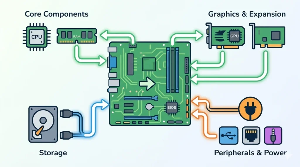
The motherboard is the main circuit board of a computer. It is the foundational layer upon which every other hardware component either directly mounts or connects through cables and slots. The CPU plugs into its socket on the motherboard; RAM slots into its DIMM slots; the graphics card clips into its PCIe slot; storage devices connect through its SATA or M.2 interfaces; and all of them receive electrical power through connectors on the motherboard. The motherboard is not merely a passive platform , it actively manages communication between all of these components, distributes power throughout the system, and hosts the firmware that initiates the entire computer when power is applied.
Despite being one of the most complex and important components in a computer, the motherboard is often overlooked in favour of more glamorous parts like the CPU or GPU. In reality, the motherboard is the component that determines which CPUs, RAM, storage devices, and expansion cards a system can use , making it one of the most consequential purchasing decisions in any computer build.
In this comprehensive guide, we will explore everything you need to know about the motherboard: its definition, history, inner workings, key components, functions, types and form factors, ports and connectors, relationships with other hardware, real-world uses, advantages and disadvantages, common problems, and maintenance tips. By the end, you will have a thorough and practical understanding of the backbone of every computer system.
What Is a Motherboard?
A motherboard, also known as a mainboard, system board, or logic board (in Apple systems), is the primary printed circuit board (PCB) in a computer. It is a large, flat board covered in electronic circuits, connectors, slots, and chips that provides the physical and electrical infrastructure for connecting and coordinating all of a computer’s hardware components.
The motherboard is often called the backbone of a computer because, like a biological backbone, it provides the central structural and communicative framework that everything else attaches to and depends upon. Every component in a computer , from the CPU and RAM to storage devices, graphics cards, and USB peripherals , ultimately connects to the motherboard either directly or indirectly. Without the motherboard, these components would have no way to communicate with each other or receive the power they need to operate.
The importance of the motherboard in computer hardware cannot be overstated. It determines the system’s overall capabilities and limitations: which generation of CPU it supports (defined by its CPU socket type), how much and what type of RAM it can accommodate, how many storage devices can be connected, what expansion cards can be installed, and what external ports are available. Choosing the right motherboard for a build is therefore one of the most important and consequential hardware decisions a builder makes.
At its most fundamental level, the motherboard serves four essential roles: it provides a physical mounting platform for components, it provides the electrical connections through which components communicate via high-speed data buses, it distributes regulated power from the power supply unit to every component, and it hosts the system firmware (BIOS or UEFI) that initialises hardware and boots the operating system every time the computer starts.
History of Motherboards
The motherboard as we know it today is the result of decades of engineering evolution, driven by the relentless push for greater performance, smaller size, and improved manufacturability.
Early Computer Circuit Boards
The earliest electronic computers of the 1940s and 1950s had no motherboards in any recognisable sense. Their circuitry was implemented through vast arrays of vacuum tubes, relays, and wiring that occupied entire rooms. The concept of a printed circuit board , a flat substrate on which conductive traces carry signals between components , was itself still new technology in this era.
Printed circuit boards were invented in the 1940s, primarily for military applications, and gradually found their way into commercial electronics through the 1950s. Early computers of the late 1950s and early 1960s, such as the IBM 1401 and the early mainframes, began using PCBs to replace hand-wired backplanes, reducing size and improving reliability. However, these early “boards” were not motherboards in the modern sense , they were functional modules, each performing a specific part of the computer’s work, connected together in large card cages.
Development of Modern Motherboards
The true ancestor of the modern motherboard emerged with the advent of the microprocessor in the early 1970s and the subsequent personal computer revolution. The Apple II (1977) and the original IBM Personal Computer (1981) both used single main circuit boards that housed the CPU, memory, and expansion slots , a layout that established the basic architectural template that motherboards follow to this day.
The IBM PC’s open architecture , which published the specifications of its system board , was particularly influential. It allowed third-party manufacturers to produce compatible motherboards, expansion cards, and peripherals, creating the ecosystem that became the PC industry. The standardisation of the AT form factor (Advanced Technology) in 1984 with the IBM AT computer established the first widely adopted motherboard size standard, defining both the physical dimensions of the board and the arrangement of its key components.
The Intel 486 era of the late 1980s and early 1990s saw motherboards grow in sophistication, integrating previously discrete functions , like the memory controller and bus controller , onto dedicated chips called chipsets. This chipset-based architecture, which remained standard for decades, allowed motherboard designs to evolve with new CPU generations while maintaining a consistent overall structure.
Evolution of Motherboard Technology
The mid-1990s brought a transformative change: the ATX (Advanced Technology Extended) form factor, introduced by Intel in 1995. ATX addressed many limitations of the AT standard with a better layout that improved airflow, easier assembly, and a standardised rear I/O panel. ATX and its derivatives (Micro-ATX, Mini-ITX, E-ATX) became the dominant motherboard standards and remain so today.
The late 1990s through the 2000s saw motherboards continuously absorbing previously discrete components: integrated audio (sound cards became unnecessary for most users), integrated networking (network interface cards became standard), integrated video (adequate for basic use), and eventually support for USB, FireWire, SATA, and PCIe. Each successive chipset generation from Intel and AMD brought support for faster RAM, faster interconnects, and new storage technologies.
A particularly significant evolution was the shift of the memory controller from the motherboard chipset into the CPU itself , pioneered by AMD’s Athlon 64 in 2003 and subsequently adopted by Intel with its Nehalem architecture in 2008. This “on-die” memory controller dramatically reduced memory latency and improved performance, and it also changed how motherboards were designed, reducing the chipset’s role in memory management.
Future Trends in Motherboard Design
Modern motherboard development is being shaped by several emerging trends. The shift toward PCIe 5.0 and soon PCIe 6.0 interconnects is enabling dramatically faster storage and GPU communication. The growing prevalence of high-speed M.2 NVMe storage , now a standard feature on even budget motherboards , has reduced reliance on traditional SATA connections. USB4 and Thunderbolt 4/5 ports are increasingly appearing on mainstream boards, providing versatile, high-speed connectivity for external devices.
The integration of Wi-Fi 6E and Wi-Fi 7 directly onto motherboards is eliminating the need for separate wireless network cards in most builds. Power delivery systems are becoming increasingly sophisticated to support the high power demands of modern multi-core CPUs. And in the longer term, the industry is exploring three-dimensional integration of components , stacking memory, chiplets, and other elements , that may eventually change the fundamental architecture of how motherboards and the chips they host are designed.
How Does a Motherboard Work?
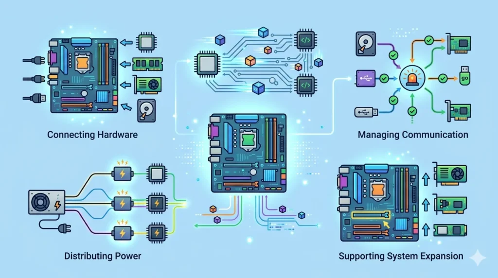
The motherboard works by providing the physical infrastructure and electrical pathways through which all computer components communicate, receive power, and operate in coordination. Its operation can be understood across four key functions:
Connecting Hardware Components
The motherboard’s most visible function is providing the physical connection points for all of a computer’s hardware. The CPU socket accepts the processor and locks it into place with a lever mechanism or screw-down lid. DIMM slots accept RAM modules. PCIe slots accept graphics cards and other expansion cards. M.2 slots and SATA connectors accept storage devices. Fan headers connect cooling fans. Power connectors receive cables from the power supply. All of these connections are physical interfaces that are precisely engineered to match the components they accept, ensuring correct installation and reliable electrical contact.
The physical traces etched into the motherboard’s PCB , the microscopic copper pathways that run between components , carry electrical signals between these connection points at high speed. A modern motherboard’s PCB typically has six to ten or more layers of copper traces, each layer separated by insulating material, allowing thousands of signal paths to cross and interconnect without shorting each other.
Data Communication Between Devices
Beyond physically connecting components, the motherboard manages the flow of data between them. Different components communicate over different buses , standardised electrical pathways with defined protocols, speeds, and widths. The CPU communicates with RAM over the memory bus at speeds of tens of gigabytes per second. PCIe lanes carry data between the CPU and the GPU (and other expansion cards) at up to 32 GB/s per direction for PCIe 4.0 x16 connections. The chipset manages communication between the CPU and storage devices, USB controllers, audio chips, and other peripherals over the PCH (Platform Controller Hub) interconnect.
The chipset , a chip or set of chips on the motherboard , plays a central role in this communication management. It acts as a traffic controller, routing data between components, managing access to shared resources, and handling communication with devices that are not connected directly to the CPU. Modern chipsets from Intel (e.g., Z790, B760) and AMD (e.g., X670E, B650) define much of a motherboard’s feature set, determining how many PCIe lanes are available, how many USB ports are supported, and what storage options are offered.
Power Distribution
The motherboard distributes electrical power from the power supply unit (PSU) to every component in the system. The PSU connects to the motherboard through a 24-pin ATX main power connector, which provides power for most of the board’s functions, and a separate 4-pin or 8-pin EPS connector that specifically powers the CPU’s voltage regulator modules (VRMs). The VRMs on the motherboard are critical components: they take the 12V input from the PSU and step it down to the precise, stable, low voltages (typically 0.7–1.5V) that the CPU requires, with sufficient current to power all of its billions of transistors.
The quality and complexity of a motherboard’s power delivery system , the number of VRM phases, the quality of the MOSFETs and capacitors, and the design of the power delivery network , directly affects the CPU’s stability and overclocking potential. High-end motherboards designed for overclocking feature elaborate multi-phase VRM systems with premium components and large heatsinks, while budget boards have simpler power delivery systems adequate for stock-speed operation.
Supporting Computer Operations
The motherboard also hosts the system firmware , the BIOS (Basic Input/Output System) or its modern successor, the UEFI (Unified Extensible Firmware Interface) , stored on a small flash memory chip on the board. When the computer is powered on, this firmware is the first code that runs. It performs the POST (Power-On Self-Test) to verify that all hardware is functioning correctly, initialises and configures hardware components, and then locates and loads the operating system from storage. Without the BIOS/UEFI firmware on the motherboard, the computer would have no way to start up.
Additionally, the motherboard contains a small battery (typically a CR2032 coin cell) that powers a tiny chip called the RTC (Real-Time Clock), which keeps track of the date and time even when the computer is powered off. This battery also preserves BIOS/UEFI settings in CMOS memory, so custom configurations (boot order, fan curves, overclocking settings) are retained between sessions.
Main Components of a Motherboard
A modern motherboard is populated with a diverse array of components, each serving a specific purpose within the system. Understanding these components helps explain what a motherboard does and why each element matters:
1. CPU Socket
The CPU socket is the most prominent feature of a motherboard , a square or rectangular connector array, typically located in the upper-left quadrant of the board, where the processor is installed. The socket type determines which CPUs are compatible with the motherboard: Intel’s LGA (Land Grid Array) sockets have pins on the socket and pads on the CPU, while AMD’s AM5 socket (and older AM4) have pins on the CPU and pads in the socket.
Each generation of CPUs typically introduces a new socket standard. Intel’s LGA1700 socket supports 12th and 13th generation Core processors; its successor LGA1851 supports Intel Core Ultra 200 series processors. AMD’s AM5 socket, introduced with Ryzen 7000, is intended to support multiple CPU generations. When choosing a motherboard, the CPU socket is the first and most critical compatibility check , a CPU will physically only fit in its matching socket type.
2. RAM Slots
DIMM (Dual In-line Memory Module) slots are the long, thin connectors that accept RAM modules. Most consumer motherboards feature two or four DIMM slots, while high-end and server boards may have eight or more. The slots are typically colour-coded in pairs to indicate optimal dual-channel configuration , installing RAM in matching pairs activates dual-channel mode, which doubles the memory bandwidth available to the CPU and improves performance.
DIMM slots are generation-specific: a DDR4 motherboard has DDR4 slots with a specific notch position, while a DDR5 motherboard has DDR5 slots with a different notch position. The two are physically incompatible, preventing incorrect installation. Each motherboard specifies the maximum supported RAM capacity (e.g., up to 128GB) and the supported RAM speeds and timings through its QVL (Qualified Vendor List).
3. Chipset
The chipset is a chip (or historically, a pair of chips called the northbridge and southbridge) on the motherboard that manages communication between the CPU and the system’s peripherals. In modern systems, the northbridge’s functions , memory controller and CPU-to-PCIe communication , have been integrated directly into the CPU die, leaving the chipset (now a single-chip solution sometimes called the PCH, or Platform Controller Hub) to handle slower peripherals: USB ports, SATA connectors, additional PCIe lanes for storage and network cards, and audio.
The chipset determines much of a motherboard’s feature set. Higher-end chipsets (like Intel’s Z790 or AMD’s X670E) offer more PCIe lanes, more USB ports, full CPU overclocking support, and greater connectivity options. Mid-range chipsets (B760, B650) offer a balanced feature set at lower cost, while budget chipsets (H610, A620) reduce feature counts to minimise price.
4. BIOS/UEFI Chip
The BIOS/UEFI chip is a small flash memory chip on the motherboard that stores the system firmware , the foundational software that runs when the computer is first powered on. Modern motherboards use UEFI (Unified Extensible Firmware Interface), which offers a graphical interface, mouse support, support for large storage drives (over 2TB), secure boot capabilities, and network-based firmware updates, all improvements over the older text-based BIOS standard.
The UEFI firmware performs the POST, configures hardware, and loads the operating system. It also provides the interface for adjusting hardware settings , memory speeds and timings (XMP/EXPO profiles), CPU overclocking parameters, fan curves, boot device order, and security settings. Motherboard manufacturers periodically release UEFI updates that add support for new CPUs, fix bugs, and improve stability, making UEFI updates an important part of system maintenance.
5. Expansion Slots
PCIe (Peripheral Component Interconnect Express) slots are the long, low-profile connectors used to install expansion cards , most importantly the graphics card, but also network cards, sound cards, capture cards, PCIe SSD cards, and many other devices. PCIe slots come in different physical sizes designated by their lane count: x1 (smallest), x4, x8, and x16 (largest, used for graphics cards).
The number and configuration of PCIe slots varies by motherboard tier: high-end boards may feature multiple full-length x16 slots for multi-GPU or GPU-plus-capture-card configurations, while budget boards may have a single x16 slot and one or two x1 slots. Modern PCIe generations (4.0 and 5.0) offer progressively higher bandwidth, with PCIe 5.0 x16 providing up to 128 GB/s of bidirectional bandwidth , more than enough for even the most demanding graphics cards and NVMe storage devices.
6. Storage Connectors
Motherboards provide multiple types of storage connectors to accommodate different storage technologies. SATA (Serial ATA) connectors , small, L-shaped 7-pin ports , support traditional hard disk drives (HDDs) and SATA SSDs. Most motherboards include four to eight SATA ports, each capable of sustaining up to 600 MB/s transfer speeds. While SATA remains widely used, its speed ceiling is increasingly a limitation compared to faster alternatives.
M.2 slots are small, horizontal connectors that accept M.2 NVMe SSDs , compact, card-like storage devices that plug directly into the motherboard without needing a cable. M.2 NVMe drives using PCIe 4.0 can sustain sequential read speeds exceeding 7,000 MB/s, while PCIe 5.0 M.2 drives push beyond 14,000 MB/s. Modern motherboards typically include two to five M.2 slots, with many boards providing thermal shields (heatsinks) over the slots to keep fast NVMe drives cool.
7. Power Connectors
The motherboard receives electrical power from the PSU through dedicated power connectors. The primary connection is the 24-pin ATX power connector , a wide, multi-row connector that supplies multiple voltage rails (+12V, +5V, +3.3V) to the board’s various circuits. A secondary 4-pin or 8-pin EPS 12V connector supplies dedicated power specifically for the CPU’s voltage regulator modules; high-end boards may feature two 8-pin CPU power connectors to handle the power demands of high-core-count, overclockable processors.
Additional power connectors on the motherboard include fan headers (4-pin PWM connectors for CPU and case fans), RGB lighting headers for addressable LED strips and components, headers for front panel connectors (power button, reset button, power LED, HDD activity LED), and USB headers for the case’s front-panel USB ports. Each of these connectors plays a specific role in the system’s power delivery or control infrastructure.
8. Input/Output Ports
The rear I/O panel of a motherboard , the cluster of ports accessible from the back of the computer case , provides the connection points for external devices. A modern motherboard’s rear I/O typically includes multiple USB Type-A and Type-C ports across several USB generations (USB 3.2 Gen 2, USB4, Thunderbolt 4/5 on higher-end boards), an HDMI or DisplayPort output (for systems with integrated CPU graphics), a 2.5 Gigabit or faster Ethernet port, and a set of 3.5mm audio jacks for speakers, headphones, and microphones. Many modern boards also integrate a Wi-Fi antenna connector for built-in wireless networking.
The quality and quantity of rear I/O ports is a significant differentiator between motherboard tiers. Budget boards may offer basic USB connectivity and a single network port, while premium boards may feature USB4 40Gbps ports, Thunderbolt 5, 10 Gigabit Ethernet, Wi-Fi 7, and a full complement of audio outputs including optical S/PDIF.
Functions of a Motherboard
The motherboard performs five fundamental functions that collectively make a computer system operational:
1. Connecting Hardware Components
The motherboard’s most essential function is serving as the universal connection platform for all computer hardware. It provides precisely engineered sockets, slots, and headers that allow the CPU, RAM, GPU, storage devices, cooling systems, and peripheral connections to interface with the system in a standardised way. Without this central connection platform, each component would have no standardised way to physically interface with others, making a coherent computer system impossible to assemble.
2. Facilitating Data Transfer
The motherboard facilitates the continuous, high-speed transfer of data between all connected components. Copper traces on the PCB, operating as data buses, carry information between the CPU and RAM, between the CPU and expansion cards via PCIe lanes, and between the chipset and storage devices, USB controllers, and other peripherals. Each bus operates at a defined speed and width, and the motherboard’s design , the routing of traces, the quality of signal integrity, and the capabilities of the chipset , determines how efficiently data flows through the system.
3. Managing Communication
The motherboard’s chipset manages and arbitrates communication between components that need to share access to common resources. When multiple devices need to transfer data simultaneously , for example, when the CPU is reading from RAM, a storage device is transferring a file through the chipset, and a USB device is sending data , the chipset coordinates these transfers, prioritising them according to defined protocols to ensure data arrives at the right destination at the right time without conflicts or data corruption.
4. Distributing Power
The motherboard receives raw power from the PSU and distributes regulated, precise voltages to every component in the system. The voltage regulator modules (VRMs) on the motherboard are critical for this function: they take the 12V input and step it down to the exact voltages required by the CPU (which may vary dynamically based on workload). Stable, clean power delivery is essential for system stability and component longevity. A motherboard with a well-designed power delivery system protects components from voltage fluctuations and ensures they operate within their specified electrical parameters.
5. Supporting System Expansion
The motherboard enables system expansion through its PCIe slots, M.2 slots, and additional connectors. Users can add a dedicated graphics card for gaming or content creation, install a high-speed NVMe SSD for improved storage performance, add a Wi-Fi or network card for connectivity, install a professional audio card for recording, or connect a capture card for streaming. The number and type of expansion options a motherboard provides determines how the system can grow and adapt to changing needs over time, making expansion capability an important consideration for builders who anticipate future upgrades.
Types of Motherboards
Motherboards are available in several distinct types, primarily differentiated by their form factor (physical size) and feature set, each suited to different use cases:
a. ATX Motherboard
ATX (Advanced Technology Extended) is the most common and widely used motherboard form factor, measuring 305mm × 244mm (12″ × 9.6″). Introduced by Intel in 1995 as an improvement over the older AT standard, ATX motherboards offer the most comprehensive feature sets among consumer boards, typically providing four or more DIMM slots, multiple PCIe expansion slots (including two or more full-length x16 slots on higher-end models), numerous M.2 and SATA connectors, and a full-featured rear I/O panel.
ATX boards are the preferred choice for desktop PC builds where space is not a constraint , gaming desktops, workstations, and enthusiast builds all commonly use ATX. The extra physical space allows board manufacturers to include more VRM phases for better CPU power delivery, more expansion slots for greater flexibility, and premium features like onboard debug LEDs, POST code displays, and extensive RGB lighting. ATX boards require mid-tower or full-tower cases.
b. Micro-ATX Motherboard
Micro-ATX (mATX) motherboards measure 244mm × 244mm , a square form factor that is smaller than full ATX while still fitting in most standard mid-tower cases. Micro-ATX boards represent the most popular balance between size and features: they typically offer two to four DIMM slots, two to four PCIe slots (usually one full-length x16 slot), and a good selection of storage connectors and rear I/O ports, while fitting in more compact cases than full ATX.
Micro-ATX is the go-to choice for cost-conscious builds, home office computers, and compact gaming systems where a full-size board is unnecessary. The smaller PCB means fewer expansion slots and sometimes fewer VRM phases than equivalent ATX boards, but for users who do not plan to install multiple expansion cards, the trade-off is generally worthwhile for the savings and compact footprint.
c. Mini-ITX Motherboard
Mini-ITX motherboards are compact boards measuring just 170mm × 170mm (6.7″ × 6.7″), making them the smallest standard consumer motherboard form factor. Despite their small size, Mini-ITX boards typically feature a single PCIe x16 slot for a graphics card, two DIMM slots, and one or two M.2 slots, along with a full rear I/O panel , everything needed for a complete, capable computer system.
Mini-ITX boards are designed for small form factor (SFF) computers , compact, space-efficient builds for living rooms, offices with limited desk space, or portable LAN party systems. The trade-offs for compactness are significant: only two RAM slots (limiting maximum memory capacity), a single expansion slot, and in many cases, higher prices despite fewer features (due to the engineering challenge of fitting everything into a small, densely packed PCB). However, for users who prioritise a small footprint, Mini-ITX enables surprisingly capable systems in remarkably small cases.
d. Extended ATX (E-ATX)
Extended ATX (E-ATX) motherboards are larger than standard ATX, measuring 305mm × 330mm or larger. These oversized boards are designed for high-performance workstations, enthusiast-grade desktop builds, and some server applications. E-ATX motherboards typically feature eight DIMM slots for maximum RAM capacity (up to 256GB or more), multiple full-length PCIe slots for multi-GPU or GPU-plus-expansion configurations, extensive M.2 and SATA storage connectivity, and elaborate power delivery systems for extreme overclocking.
E-ATX boards require full-tower or purpose-built cases to accommodate their larger dimensions. They are used by professionals who demand maximum expandability , 3D artists running multiple GPUs, video editors with enormous RAM requirements, and overclocking enthusiasts pushing hardware to its limits. For the vast majority of users, E-ATX is unnecessary, but for those who need every feature available, it represents the pinnacle of consumer motherboard capability.
Form Factors of Motherboards
Motherboard form factors define standardised physical dimensions, mounting hole positions, and connector placements that ensure compatibility between motherboards and computer cases. Understanding form factors is essential for selecting a case that will physically fit your chosen motherboard:
ATX
ATX measures 305mm × 244mm and is the dominant consumer form factor for desktop computers. Its size accommodates the full range of features most users want , multiple expansion slots, four DIMM slots, comprehensive rear I/O , without being unnecessarily large. ATX cases range from mid-tower to full-tower and are widely available from all major case manufacturers. The ATX standard defines seven mounting hole positions on the board that align with corresponding standoffs in compatible cases.
Micro-ATX
Micro-ATX measures 244mm × 244mm and fits in both Micro-ATX cases (which are smaller than mid-tower ATX cases) and most standard mid-tower cases that also support ATX (since the mounting holes are in compatible positions). This flexibility makes Micro-ATX a versatile choice , buyers can opt for a smaller case to save desk space or use a standard case if they prefer the additional internal space for cable management and airflow.
Mini-ITX
Mini-ITX measures 170mm × 170mm and requires a dedicated Mini-ITX case , it is too small to properly mount in a standard ATX or Micro-ATX case. Mini-ITX cases come in an enormous variety of designs, from ultra-compact shoebox-sized enclosures to slightly larger designs that accommodate full-height graphics cards and 240mm liquid coolers. The Mini-ITX standard has a single mounting hole at each corner of the board. Building in Mini-ITX cases requires careful planning around cooling, cable routing, and component selection due to the tight space constraints.
E-ATX
E-ATX boards are larger than ATX at 305mm × 330mm (or larger for some server/workstation variants), requiring full-tower cases or purpose-built workstation chassis. Not all full-tower cases support E-ATX , buyers must verify case specifications before purchasing. E-ATX is a less standardised form factor than ATX or Micro-ATX; board dimensions and mounting hole positions can vary between manufacturers, so case-board compatibility requires careful verification. E-ATX cases typically feature extensive cable management options and support for multiple radiators, large air coolers, and numerous drive bays.
Motherboard Ports and Connectors
Motherboards provide a rich variety of ports and connectors, both on the rear I/O panel (for external devices) and internally (for case connections and internal components):
1. USB Ports
USB (Universal Serial Bus) ports are the most widely used external connectors on a motherboard, enabling connection of keyboards, mice, flash drives, external drives, smartphones, headsets, and countless other peripherals. Modern motherboards feature multiple USB generations on their rear I/O panel: USB 3.2 Gen 1 (5 Gbps), USB 3.2 Gen 2 (10 Gbps), USB 3.2 Gen 2×2 (20 Gbps), and increasingly USB4 (40 Gbps) and Thunderbolt 4/5 on premium boards. Both Type-A (the rectangular connector most users recognise) and Type-C (the smaller, oval reversible connector) are commonly found. Internally, motherboards provide USB headers for connecting front-panel USB ports on the case.
2. HDMI and Display Ports
Motherboards with integrated CPU graphics (present in most Intel-based boards and boards paired with AMD APUs) include video output ports on the rear I/O panel , typically HDMI and/or DisplayPort. These ports allow the computer to output video to a monitor directly from the CPU’s integrated graphics, without requiring a discrete graphics card. For users performing basic computing tasks , office work, web browsing, media playback , integrated graphics output through these motherboard ports is sufficient. Users with discrete graphics cards typically use the ports on the GPU instead, bypassing the motherboard’s video output ports.
3. Ethernet Port
The Ethernet port (RJ-45) on the motherboard’s rear I/O provides wired network connectivity. Most modern consumer motherboards include at least one 2.5 Gigabit Ethernet port , a significant upgrade over the 1 Gigabit Ethernet that was standard for many years. High-end motherboards may include a 10 Gigabit Ethernet port for users with compatible network infrastructure. Wired Ethernet connections are preferred over Wi-Fi for gaming, video conferencing, and file transfers due to their lower latency, higher reliability, and consistent throughput.
4. Audio Ports
The rear I/O panel includes a set of 3.5mm audio jacks for analog audio input and output. A typical multi-channel audio setup includes connectors for front left/right speakers, rear left/right speakers, centre speaker and subwoofer, a side surround pair, a microphone input, and a line-in for recording from external audio sources. Premium motherboards include optical S/PDIF digital audio output for connecting to home theatre receivers and high-quality DAC/amplifier systems. Internally, motherboards include front-panel audio headers for connecting the case’s front-panel headphone and microphone jacks.
5. SATA Connectors
SATA (Serial ATA) connectors , small, right-angle 7-pin ports , are used to connect HDDs, SATA SSDs, and optical drives. Most motherboards provide four to eight SATA ports, each capable of sustaining data transfer speeds up to 600 MB/s (SATA III). While SATA storage remains common and cost-effective for mass storage (particularly large-capacity HDDs), NVMe SSDs via M.2 slots have become the preferred choice for operating system and primary application drives due to their dramatically higher performance.
6. M.2 Slots
M.2 slots accept M.2 form factor drives, which can be either NVMe (PCIe-based, very fast) or SATA-based. NVMe M.2 drives connect directly to PCIe lanes (from the CPU or chipset), bypassing the SATA controller entirely and achieving sequential read speeds of 3,500 MB/s to over 14,000 MB/s depending on the PCIe generation. Modern motherboards typically provide two to five M.2 slots, and most include integral heatsinks (metal plates with thermal pads) over the slots to prevent NVMe drives from thermal throttling under sustained load. The M.2 interface has become the standard for high-performance storage in modern systems.
Motherboard and Other Hardware Components
The motherboard’s defining characteristic is that it serves as the integration point for all other hardware. Understanding how the motherboard relates to each major component reveals why it is so central to a computer’s design:
Motherboard and CPU
The relationship between the motherboard and CPU is the most fundamental compatibility constraint in any computer build. The CPU physically plugs into the motherboard’s CPU socket, which is socket-type-specific , Intel CPUs use LGA sockets (like LGA1700 or LGA1851) while AMD CPUs use AM4 or AM5 sockets, and these are completely incompatible with each other. Beyond physical compatibility, the motherboard’s chipset and UEFI firmware must support the specific CPU being installed; a motherboard may require a UEFI update to support a newer CPU released after the board’s launch.
The motherboard also directly supports the CPU’s performance through its VRM (voltage regulator module) system. Higher-quality VRMs with more phases deliver cleaner, more stable power to the CPU, which is essential for overclocking and for maintaining stability under sustained high-core-count workloads. The motherboard also provides the CPU socket’s retention mechanism, which ensures the CPU makes reliable contact with all socket pins while allowing easy removal for upgrades.
Motherboard and RAM
The motherboard determines what type, speed, and maximum capacity of RAM a system can use. DDR4 and DDR5 RAM are not interchangeable , a DDR5 motherboard only accepts DDR5 RAM, and a DDR4 board only accepts DDR4, enforced by physically different notch positions in the DIMM slots. The motherboard also specifies the maximum supported RAM speed (in MHz) and the officially supported memory kits through its QVL (Qualified Vendor List).
The number of DIMM slots on the motherboard caps the total RAM capacity: with four slots and DDR5 modules up to 64GB per stick, a motherboard could support up to 256GB. RAM installed in matching pairs activates dual-channel mode, doubling the memory bandwidth , a feature the motherboard’s memory controller (now integrated into the CPU) enables based on how the DIMM slots are populated. Running RAM in XMP (Intel) or EXPO (AMD) mode , at speeds higher than the base JEDEC spec , is configured through the UEFI firmware on the motherboard.
Motherboard and GPU
The graphics card connects to the motherboard through its primary PCIe x16 slot , typically the topmost full-length slot on the board, which is wired directly to the CPU’s PCIe lanes for maximum bandwidth. Modern PCIe 4.0 x16 connections provide up to 32 GB/s of bandwidth in each direction, and PCIe 5.0 x16 doubles that to 64 GB/s , far more than even the most powerful current GPUs require.
For systems with integrated GPU graphics (no discrete card), the motherboard routes video output from the CPU’s iGPU through the rear I/O panel’s HDMI or DisplayPort outputs. High-end motherboards designed for enthusiast builds may feature multiple PCIe x16 slots for multi-GPU configurations (though multi-GPU gaming support has waned in recent years), GPU-plus-capture-card setups, or professional compute configurations using multiple GPU accelerators.
Motherboard and Storage Devices
The motherboard connects to storage devices through its SATA ports (for HDDs and SATA SSDs), M.2 slots (for NVMe and SATA M.2 drives), and in some cases through additional PCIe slots (for PCIe SSD add-in cards). The SATA controller is part of the motherboard’s chipset and manages communication between the CPU and SATA-connected devices. M.2 NVMe drives may connect either directly to the CPU’s PCIe lanes (CPU-attached M.2) or to the chipset (chipset-attached M.2) , CPU-attached slots offer lower latency and are preferred for the primary NVMe drive.
The motherboard’s UEFI firmware manages the boot configuration for storage devices, determining which drive the system attempts to boot from first. Modern UEFI supports the NVMe Boot specification, allowing the system to boot directly from NVMe SSDs , a capability that was not available in older BIOS systems, which could only boot from SATA and USB devices.
Uses of a Motherboard
Motherboards are universal components found in virtually every computing device, from consumer desktops to enterprise servers:
Desktop Computers
The desktop computer is the most familiar application of the motherboard. In a desktop, the motherboard sits inside a tower or compact case, accepting the user’s chosen CPU, RAM, and storage devices, and providing the expansion slots for graphics cards and other peripherals. Desktop motherboards offer the greatest range of form factors, feature sets, and price points of any segment, from entry-level budget boards costing under fifty dollars to flagship enthusiast boards with every conceivable feature costing several hundred dollars.
Laptops
Laptop motherboards , often called logic boards in Apple systems , are highly compact, custom-designed circuit boards specific to each laptop model. Unlike desktop motherboards, laptop boards are not standardised: the CPU, RAM (in many modern laptops), and even storage are soldered directly to the board, making upgrades impossible. The laptop motherboard integrates all components , CPU, GPU, RAM, storage, Wi-Fi, Bluetooth, audio, display controller, battery management, and all ports , into a single, densely packed board designed to fit within the laptop’s slim chassis. The consequence of this integration is that a failing motherboard in a laptop is often catastrophic , replacing it typically costs more than a significant fraction of the laptop’s original price.
Gaming PCs
Gaming PC builds typically use mid-range to high-end ATX or Micro-ATX motherboards that offer robust power delivery for overclockable CPUs, PCIe 4.0 or 5.0 connectivity for fast GPUs and NVMe storage, multiple M.2 slots for storage, and comprehensive rear I/O. Gaming motherboards from manufacturers like ASUS ROG, MSI MEG/MPG, Gigabyte AORUS, and ASRock Taichi often add gaming-specific features: onboard debug LEDs and POST code displays, BIOS flashback for CPU-less UEFI updates, reinforced PCIe and DIMM slots for heavy GPU installation, and elaborate RGB lighting systems.
Workstations
Professional workstation motherboards are designed for demanding computational workloads , 3D rendering, video production, scientific simulation, financial modelling, and AI development. Workstation boards often support the highest-end consumer or server-grade CPUs (like AMD’s Threadripper or Intel’s Xeon W series), ECC (Error-Correcting Code) RAM that automatically corrects single-bit memory errors for data integrity, multiple GPU slots for professional compute acceleration, and extensive storage connectivity. These boards prioritise reliability, stability, and maximum expandability over gaming-specific features.
Servers
Server motherboards are purpose-designed for continuous, mission-critical operation in data centres and enterprise environments. They feature multi-socket designs supporting two or more server-grade CPUs (Intel Xeon or AMD EPYC), support for massive RAM capacities (often over 1TB through many DIMM slots), redundant power delivery systems, remote management capabilities (IPMI/BMC) for server administration without physical access, and extensive PCIe expansion for network interface cards, storage controllers, and accelerators. Server motherboards prioritise reliability, redundancy, and manageability over the consumer features found on desktop boards.
Advantages of a Motherboard
Centralized Hardware Connection
The motherboard’s greatest advantage is that it provides a single, centralised platform for connecting all hardware components. Instead of requiring custom interfaces between every pair of components , which would be impractical and expensive , the motherboard defines standardised connection points that any compatible component can use. This centralisation makes computer assembly straightforward: builders select compatible components, plug them into the appropriate slots on the motherboard, and the system is ready to function. The motherboard turns a collection of individual components into an integrated, working computer.
Easy Component Communication
By hosting the chipset and providing the data buses that connect components, the motherboard enables seamless, high-speed communication between all hardware without requiring users to configure or understand the underlying communication protocols. The CPU can read from RAM, write to an NVMe drive, send draw calls to the GPU, and receive input from a USB keyboard , all simultaneously , because the motherboard’s infrastructure handles the routing and coordination of these data flows transparently.
Supports Upgrades
A good motherboard extends the upgradeability of a computer system. A motherboard with a CPU socket that spans multiple CPU generations allows users to upgrade to a newer, faster processor without replacing the entire board. Additional RAM slots allow memory capacity to be expanded. Extra M.2 and SATA connectors allow storage to grow. Spare PCIe slots allow new expansion cards to be added. This upgradeability means that a well-chosen motherboard can anchor a system through several rounds of component upgrades, representing better long-term value than boards with minimal expansion options.
Enables Efficient System Performance
A high-quality motherboard enables the full performance potential of installed components. A robust VRM system allows the CPU to operate stably at its maximum boost clocks , and beyond, for overclocking enthusiasts. Support for XMP/EXPO RAM profiles unlocks the full rated speed of high-performance RAM modules. PCIe 4.0 or 5.0 connectivity ensures that a fast NVMe SSD or GPU operates at its rated bandwidth. Comprehensive thermal monitoring and fan control capabilities allow the system to maintain optimal temperatures without excessive noise. The motherboard, in short, is what allows each component to perform as designed.
Disadvantages of a Motherboard
Can Be Expensive
High-end motherboards carry substantial price tags. Flagship enthusiast motherboards from premium brands can cost as much as or more than a capable mid-range CPU, representing a significant fraction of a build’s total budget. Even mid-range boards can be expensive relative to the other components in a budget build. The price of a motherboard is justified by its VRM quality, feature set, build quality, and manufacturer support, but for users who do not need premium features, overspending on a motherboard offers diminishing returns.
Failure Affects Entire System
The motherboard’s central role in the computer system is also its greatest risk factor: if the motherboard fails, the entire computer becomes non-functional. A dead motherboard means no CPU execution, no RAM access, no storage connectivity, and no output , the system simply will not work until the motherboard is repaired or replaced. Diagnosing a motherboard failure can be difficult, as its symptoms (failure to boot, random crashes, component detection failures) overlap with the symptoms of other hardware failures. Motherboard replacement also involves removing and reinstalling all other components, making it a labour-intensive repair.
Compatibility Limitations
Each motherboard is compatible with only a specific set of CPUs (defined by the socket type), only specific generations of RAM (DDR4 or DDR5, not both), and components within the specifications of its chipset and PCIe support. This means that a motherboard purchased for an Intel 13th-generation CPU may not be usable with a 14th or 15th-generation CPU if Intel changes its socket. Similarly, upgrading from a DDR4 platform to DDR5 requires replacing both the motherboard and all RAM, adding to the upgrade cost. Compatibility limitations mean that selecting a motherboard involves careful long-term planning.
Difficult Repairs
When a motherboard fails partially , a single USB port stops working, an M.2 slot becomes unreliable, a PCIe slot loses connection , repairs are extremely difficult for most users. Unlike a failed storage drive or RAM stick that can simply be swapped out, motherboard-level repairs typically require soldering skills and specialised equipment to address at the component level. Most consumers who face a motherboard failure must choose between replacing the entire board (expensive) or paying a professional repair service (also expensive and not always successful). This repairability challenge makes motherboard quality and reliability an important consideration in the initial purchase.
Common Motherboard Problems
Recognising common motherboard problems early can prevent data loss and system damage:
Failure to Boot
The most dramatic motherboard symptom is a complete failure to boot , pressing the power button produces no response, or the system powers on briefly then immediately powers off. This can be caused by a blown fuse or capacitor on the motherboard, a failed VRM, a short circuit from improper installation, or a corrupted UEFI firmware. Diagnosis typically involves removing all non-essential components (RAM, GPU, storage) and attempting to boot with the minimum required components, listening for BIOS speaker beep codes that indicate the specific fault.
Overheating
Motherboard components , particularly the VRM MOSFETs and chipset , can overheat in systems with poor airflow or during extreme overclocking. Overheating VRMs cause the CPU to throttle (reduce its clock speed to reduce power consumption) or the system to crash and shut down. Modern high-end motherboards include large heatsinks over the VRM and chipset, and some feature integrated cooling fans on the VRM heatsink. Ensuring adequate case airflow and monitoring VRM temperatures with tools like HWiNFO is important for maintaining motherboard health in thermally demanding systems.
Hardware Detection Issues
Intermittent or persistent failure to detect installed components , RAM not recognised, an M.2 drive missing from the UEFI, a PCIe device not appearing in Device Manager , can indicate a faulty slot, a UEFI compatibility issue, or physical damage to connector pins. Reseating components (removing and reinstalling them to refresh the electrical contact), testing components in different slots, and updating the UEFI firmware often resolve detection issues. Persistent detection failures in a specific slot or port may indicate physical damage to the motherboard that requires professional assessment.
Damaged Ports or Slots
Physical damage to rear I/O ports , bent USB connector receptacles, a cracked HDMI port, a damaged Ethernet jack , and internal slots , a broken PCIe slot locking latch, damaged DIMM slot tabs, bent M.2 connector pins , are common issues, particularly in older systems or those that have been moved frequently. Damaged ports can cause intermittent connectivity, device detection failures, or complete loss of function for the affected port. Physical port damage is generally not user-repairable without soldering expertise and must either be worked around (using alternative ports or a PCIe expansion card to replace the failed built-in functionality) or professionally repaired.
Tips to Maintain a Motherboard
Proper maintenance extends the life of a motherboard and prevents the common issues described above:
Keep the System Clean
Dust accumulation inside a computer case is one of the primary causes of overheating and premature component failure. Dust settles on the motherboard’s surface, particularly on heatsinks and fans, reducing thermal dissipation. Dust on PCB traces and connector contacts can cause intermittent electrical issues. Every three to six months, use compressed air to blow dust from the motherboard, VRM and chipset heatsinks, expansion slots, RAM slots, and all internal fan headers. Ensure the computer is powered off and ideally unplugged before cleaning.
Ensure Proper Cooling
Adequate airflow through the computer case is essential for keeping the motherboard and its components within their thermal limits. Ensure that the case has at least two case fans , typically one or more intake fans at the front and one or more exhaust fans at the rear and top , creating a consistent airflow path through the system. Ensure that cables are managed neatly so they do not obstruct airflow. If VRM or chipset temperatures are high (check with HWiNFO or similar monitoring software), consider adding directed airflow near those components or installing a case fan controller to increase fan speeds under load.
Use a Reliable Power Supply
A low-quality or failing power supply is one of the most common causes of motherboard damage. An unstable PSU that delivers voltage outside of specified tolerances can damage the motherboard’s VRM components, capacitors, and sensitive integrated circuits. A PSU that fails catastrophically can send voltage spikes through the system, potentially destroying the motherboard and all connected components simultaneously. Investing in a quality power supply from a reputable manufacturer , and replacing it after five to seven years of use , is one of the best protective measures for a motherboard’s long-term health. Using a surge-protected power strip or a UPS (Uninterruptible Power Supply) provides additional protection against power line events.
Update BIOS When Necessary
UEFI/BIOS updates from motherboard manufacturers address security vulnerabilities, fix stability bugs, improve compatibility with new CPUs and RAM kits, and sometimes add new features. Checking for UEFI updates periodically , particularly when installing a new CPU, when experiencing unexplained stability issues, or when adding new RAM that the system does not recognise correctly , is good practice. Most modern motherboards support UEFI updates directly from within the UEFI interface (downloading the update from the manufacturer’s servers) or through a feature called BIOS Flashback that updates the firmware from a USB drive without a CPU or RAM installed.
Handle Components Carefully
Physical handling mistakes are a leading cause of motherboard damage, particularly during assembly or upgrades. Always ground yourself before touching the motherboard or any component , discharge static electricity by touching a grounded metal object (like a computer case that is plugged in but switched off) or by wearing an anti-static wrist strap. Handle the motherboard by its edges and avoid touching the PCB traces, capacitors, or chip surfaces. When installing or removing the CPU, exercise extreme care , bent socket pins (in AMD’s AM4/AM5 sockets, where the pins are on the CPU) or bent socket contacts (in Intel’s LGA sockets, where the contacts are in the socket) are catastrophic and often irreparable without professional intervention.
Motherboard vs CPU
| Feature | Motherboard | CPU |
|---|---|---|
| Function | Connects and coordinates all hardware components | Processes instructions and performs calculations |
| Role | Backbone and communication hub of the computer | Brain of the computer |
| Physical Location | The main circuit board occupying the entire system | A chip installed in the CPU socket on the motherboard |
| Key Technology | PCB traces, chipset, slots, VRMs, UEFI firmware | Transistors, cores, cache, ALU, control unit |
| Performance Impact | Affects power delivery, connectivity, and stability | Directly determines processing speed and capability |
| Upgradeability | Changing CPU may require a new motherboard | CPU upgrades possible within same socket generation |
| Examples | ASUS ROG Strix Z790-E, MSI MEG X670E ACE | Intel Core i9-14900K, AMD Ryzen 9 7950X |
Motherboard vs RAM
| Feature | Motherboard | RAM |
|---|---|---|
| Function | Connects and coordinates all hardware components | Temporarily stores active data for the CPU |
| Purpose | Central communication and power distribution hub | Working memory for running applications |
| Component Type | Large printed circuit board with integrated chips | Small memory module (DIMM stick) |
| Data Storage | Does not store user data | Holds active data , lost at power off |
| Upgradeability | Complete replacement for incompatible upgrades | Can often be added or upgraded easily |
| Compatibility | Determines which RAM type is supported | Must match motherboard’s supported DDR generation |
| Examples | Gigabyte B650 AORUS Elite, ASRock Z790 Pro RS | Corsair Vengeance DDR5 32GB, G.Skill Trident Z5 |
FAQs About Motherboard
What is a motherboard in a computer?
A motherboard is the main printed circuit board (PCB) in a computer that provides the physical and electrical infrastructure connecting all hardware components. It houses the CPU socket, RAM slots, expansion slots, storage connectors, chipset, and UEFI firmware chip, and provides the data buses and power distribution pathways that allow all components to communicate and operate together as an integrated system.
Why is the motherboard important?
The motherboard is important because without it, none of the computer’s other components could communicate with each other or receive the power they need to function. It is the foundation of the entire computer system , it determines which CPUs, RAM, and storage devices the system supports, provides the expansion slots for upgrades, hosts the firmware that starts the computer, and manages the flow of data and power throughout the entire machine.
What are the main parts of a motherboard?
The main parts of a motherboard include: the CPU socket (where the processor is installed), DIMM slots (for RAM modules), the chipset (which manages communication between components and peripherals), the BIOS/UEFI chip (containing the system firmware), PCIe expansion slots (for graphics cards and other expansion cards), SATA connectors and M.2 slots (for storage devices), power connectors (for receiving power from the PSU), and the rear I/O panel (providing USB, HDMI, Ethernet, and audio ports for external devices).
What is the function of a motherboard?
The motherboard’s key functions are: connecting all hardware components through standardised slots and connectors; facilitating high-speed data transfer between components via PCB traces and data buses; managing communication between the CPU, RAM, storage, and peripherals through the chipset; distributing regulated power from the PSU to all components through VRMs and power headers; hosting the UEFI firmware that initialises hardware and boots the operating system; and supporting system expansion through expansion slots and additional connectors.
What are the different types of motherboards?
Motherboards are primarily categorised by their form factor (physical size): ATX (305mm × 244mm, the most common full-size standard), Micro-ATX (244mm × 244mm, a compact alternative fitting in most ATX cases), Mini-ITX (170mm × 170mm, designed for small form factor builds), and E-ATX (305mm × 330mm or larger, for high-end workstation and enthusiast builds). Within each form factor, boards are further differentiated by chipset tier (budget, mid-range, high-end) and feature set.
How does a motherboard connect computer components?
The motherboard connects components through physical sockets, slots, and connectors , the CPU socket accepts the processor; DIMM slots accept RAM; PCIe slots accept graphics cards and expansion cards; M.2 slots and SATA ports accept storage devices; and power connectors receive cables from the PSU. Internally, the motherboard’s PCB traces (microscopic copper pathways through multiple layers of the board) carry electrical signals between these connection points, with the chipset managing traffic coordination between components that do not connect directly to the CPU.
Can a computer work without a motherboard?
No. A computer cannot function without a motherboard. The motherboard is the essential platform that every other component depends on , for physical mounting, power delivery, and data communication. Without a motherboard, there is no way for the CPU to receive instructions or process data, no way for RAM to communicate with the processor, no way to connect storage devices, and no mechanism to start the system. The motherboard is an absolute prerequisite for a functional computer.
Conclusion
The motherboard is the unsung hero of computer hardware. While the CPU gets the glory of being the brain, and the GPU earns admiration for spectacular graphics performance, it is the motherboard that makes it all possible , providing the foundation, the connections, and the infrastructure without which none of these remarkable components could work together. It is, in the truest sense, the backbone of the computer.
Throughout this guide, we explored the full story of the motherboard: its definition as the main circuit board that connects and coordinates all hardware; its evolution from early PCBs in 1950s mainframes to the sophisticated, feature-rich boards of today; how it works by connecting components, managing data communication, distributing power, and hosting the UEFI firmware that starts the system; and its key components , CPU socket, RAM slots, chipset, BIOS/UEFI chip, PCIe slots, storage connectors, power connectors, and I/O ports , each performing a critical role.
We examined the four major form factors , ATX, Micro-ATX, Mini-ITX, and E-ATX , that suit different build types and space requirements; the motherboard’s essential relationships with the CPU, RAM, GPU, and storage devices; and its applications across desktops, laptops, gaming PCs, workstations, and servers. We also covered the advantages of centralised connectivity and upgradeability, the disadvantages of cost and compatibility constraints, common problems to watch for, and the maintenance practices that keep a motherboard healthy and reliable.
Choosing the right motherboard is one of the most important decisions in any computer build, because the motherboard determines what everything else can be. To deepen your understanding of the complete computer hardware ecosystem, explore our companion guides on the CPU , the processor that plugs into the motherboard’s socket , as well as RAM, the GPU, and storage devices such as HDDs and SSDs. Together, these components form the complete picture of how a modern computer system is designed, built, and optimised.